- 您现在的位置:买卖IC网 > Sheet目录1993 > DS1344D-33+ (Maxim Integrated Products)IC RTC SPI 3.3V 14TDFN-EP
4
Maxim Integrated
Low-Current SPI/3-Wire RTCs
DS1343/DS1344
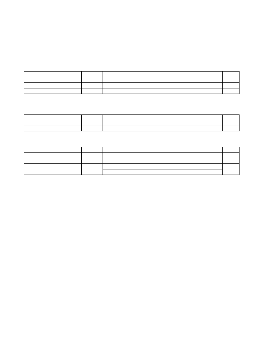
POWER-UP/DOWN CHARACTERISTICS
(TA = -40°C to +85°C, unless otherwise noted.)
CAPACITANCE
(TA = +25°C, unless otherwise noted.)
CRYSTAL PARAMETERS
Note 2: Voltage referenced to ground.
Note 3: Limits at TA = -40°C are guaranteed by design and not production tested.
Note 4: CE = VCC, VSCLK = VCC to GND, IOUT = 0mA, trickle charger disabled.
Note 5: CE = GND, IOUT = 0mA, EOSC = EGFIL = DOSF = 0, trickle charger disabled.
Note 6: VCC = 0V, EGFIL = 0, DOSF = 1.
Note 7: VCC = 0V, EGFIL = 1, DOSF = 0.
Note 8: Applies to INT0 and INT1.
Note 9: The parameter tOSF is the period of time the oscillator must be stopped for the OSF flag to be set.
Note 10: Guaranteed by design; not 100% production tested.
PARAMETER
SYMBOL
CONDITIONS
MIN
TYP
MAX
UNITS
Recovery at Power-Up
tREC
20
40
ms
VCC Fall Time (VPF to 0V)
tVCCF
150
F
s
VCC Rise Time (0V to VPF)
tVCCR
0
F
s
PARAMETER
SYMBOL
CONDITIONS
MIN
TYP
MAX
UNITS
Input Capacitance
CI
(Note 10)
10
pF
Output Capacitance
CO
(Note 10)
15
pF
PARAMETER
SYMBOL
CONDITIONS
MIN
TYP
MAX
UNITS
Nominal Frequency
fO
32.768
kHz
Series Resistance
ESR
100
kI
Load Capacitance
CL
DS1343
6
pF
DS1344
12.5
发布紧急采购,3分钟左右您将得到回复。
相关PDF资料
DS1347T+
IC RTC/CALENDAR SPI 8TDFN
DS1371U+C01
IC BINARY COUNTER 32-BIT 8-USOP
DS1372U+T&R
IC BINARY COUNTER 32-BIT 8-USOP
DS1374C-3#
IC RTC I2C W/CHARGER 16-SOIC
DS1375T+
IC RTC SERIAL W/ALARM 6-TDFN
DS1384FP-12+
IC CTRLR RTC WDOG 120NS 44-MQFP
DS1386P-8-120+
IC TIMEKEEPER RAM 64K 34-PCM
DS1388Z-3+T&R
IC RTC I2C W/CHARGER 8-SOIC
相关代理商/技术参数
DS1344D-33+T&R
制造商:Maxim Integrated Products 功能描述:SPI RTC 14P TDFN 3.3V 12.5PF AM T&R - Tape and Reel 制造商:Maxim Integrated Products 功能描述:IC RTC SPI 3.3V 14TDFN-EP 制造商:Maxim Integrated Products 功能描述:Real Time Clock Low-Current SPI/3-Wire RTC
DS1344D-33+T&R
功能描述:实时时钟 Low-Current SPI/3-Wire RTC
RoHS:否 制造商:Microchip Technology 功能:Clock, Calendar. Alarm RTC 总线接口:I2C 日期格式:DW:DM:M:Y 时间格式:HH:MM:SS RTC 存储容量:64 B 电源电压-最大:5.5 V 电源电压-最小:1.8 V 最大工作温度:+ 85 C 最小工作温度: 安装风格:Through Hole 封装 / 箱体:PDIP-8 封装:Tube
DS1344E-18+
功能描述:实时时钟 Low-Current SPI/3-Wire RTC RoHS:否 制造商:Microchip Technology 功能:Clock, Calendar. Alarm RTC 总线接口:I2C 日期格式:DW:DM:M:Y 时间格式:HH:MM:SS RTC 存储容量:64 B 电源电压-最大:5.5 V 电源电压-最小:1.8 V 最大工作温度:+ 85 C 最小工作温度: 安装风格:Through Hole 封装 / 箱体:PDIP-8 封装:Tube
DS1344E-18+T&R
制造商:Maxim Integrated Products 功能描述:SPI RTC 20P TSSOP 1.8V 12.5PF A T&R - Tape and Reel 制造商:Maxim Integrated Products 功能描述:IC RTC SPI 1.8V 20TSSOP 制造商:Maxim Integrated Products 功能描述:Real Time Clock Low-Current SPI/3-Wire RTC
DS1344E-18+T&R
功能描述:实时时钟 Low-Current SPI/3-Wire RTC
RoHS:否 制造商:Microchip Technology 功能:Clock, Calendar. Alarm RTC 总线接口:I2C 日期格式:DW:DM:M:Y 时间格式:HH:MM:SS RTC 存储容量:64 B 电源电压-最大:5.5 V 电源电压-最小:1.8 V 最大工作温度:+ 85 C 最小工作温度: 安装风格:Through Hole 封装 / 箱体:PDIP-8 封装:Tube
DS1344E-3+
功能描述:实时时钟 Low-Current SPI/3-Wire RTC
RoHS:否 制造商:Microchip Technology 功能:Clock, Calendar. Alarm RTC 总线接口:I2C 日期格式:DW:DM:M:Y 时间格式:HH:MM:SS RTC 存储容量:64 B 电源电压-最大:5.5 V 电源电压-最小:1.8 V 最大工作温度:+ 85 C 最小工作温度: 安装风格:Through Hole 封装 / 箱体:PDIP-8 封装:Tube
DS1344E-3+T&R
制造商:Maxim Integrated Products 功能描述:SPI RTC 20P TSSOP 3V 12.5PF AM T&R - Tape and Reel 制造商:Maxim Integrated Products 功能描述:IC RTC SPI 3.0V 20TSSOP
DS1344E-3+T&R
功能描述:实时时钟 Low-Current SPI/3-Wire RTC
RoHS:否 制造商:Microchip Technology 功能:Clock, Calendar. Alarm RTC 总线接口:I2C 日期格式:DW:DM:M:Y 时间格式:HH:MM:SS RTC 存储容量:64 B 电源电压-最大:5.5 V 电源电压-最小:1.8 V 最大工作温度:+ 85 C 最小工作温度: 安装风格:Through Hole 封装 / 箱体:PDIP-8 封装:Tube